Services | Condition Based Monitoring
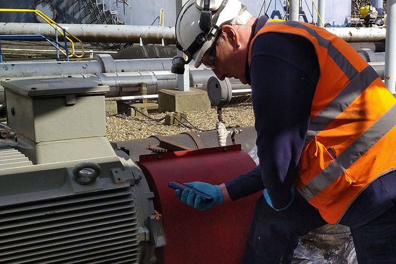
Vibration Measurement & Analysis
Regular Vibration Surveys
Vibration Analysis is the primary tool used in Condition Monitoring to analyse machine health.
- To record patterns in rotary machine behaviour and predict potential failures in advance.
- To diagnose and establish root causes of rotary asset failure
At DMS we encourage regular surveys at fixed intervals to enable our customers to build up a history of each asset and help to predict when maintenance may be required.
We hope that your vibration survey doesn’t reveal any issues. However if it does, theres no need to worry. DMS are able to carry out more detailed inspections and if necessary, utilise our associated organisations to supply, manufacture and install any replacement parts required.

Imbalance
Imbalance is diagnosed when a heavy spot is detected on a rotating asset. This is caused when the centre of rotation drifts away from the centre of mass. Left untreated, the difference increases and eventually leads to seizure.
Using the waveform created from the data, our Engineers can determine the severity and location of the imbalance and therefore recommended remedial action.
Misalignment
Misalignment occurs when the shaft centre lines of two mating components are offset. This can occur with the shafts remaining parallel, or at an angle.
Waveforms created from misalignment will typically result in repeated patterns with a dominant frequency at each revolution.
Looseness
Looseness can be either mechanical or structural. Either the component parts of the machine are not fitted together correctly or have loosened over time.
Alternatively, the foundations of the machine have become weak resulting in loose machine mounting (soft foot), degrading bedplates or loose bolts. Waveform data is often periodic with more predominant vertical amplitudes.
Bearing Damage (Rolling Element Types)
Using vibration analysis as a tool, we are able to detect various stages of bearing damage.
Bearing damage can occur for a number of reasons, such as lifetime exceeded, overload conditions, insufficient lubrication, incorrect installation, etc.
These damage conditions can be detected using vibration, identifying the bearing defect frequencies and normally result in an increase in noise (dependent on the damage occurred).
Generally most rolling element bearings consist of an inner race, outer race, cage and rolling element (such as balls, rollers, spherical rollers, taper rollers, etc).
These components will have definitive defect frequency that can be identified should we know the exact shaft rotational speed of the bearing. From the bearing geometry and rotational speed, we are able to identify the following:-
- BPFO – Ball pass frequency, outer race
- BPFI – Ball pass frequency, inner race
- BSF – Ball spin frequency
- TFT – Fundamental train frequency (eg. Cage frequency)
Al these types of defect frequencies, provide a distinct pattern that enable us to detect early stages of failure.
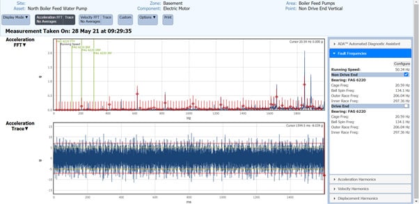
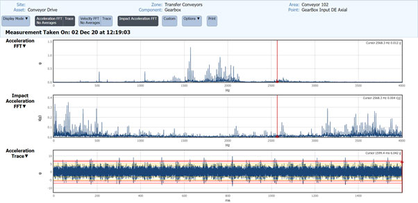
Example displaying both outer race and cage damage
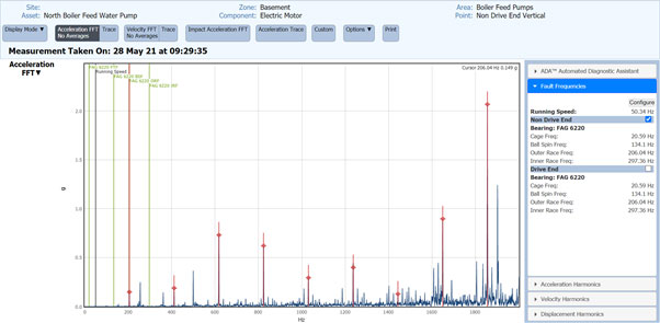
Further supporting evidence of the modulation of the bearing damage displaying outer race defects
Sleeve Bearing Wear
Sleeve bearings with excessive clearance allow small excitation forces such as imbalance to cause significant vibration amplitudes.
Spectral data typically shows predominant synchronous frequencies between approximately 1x 10x RPM depending on problem severity bearing design and application (in some cases ½ RPM and harmonics may also apply)
Blade/Vane Pass Frequency
A blade or vane excites a signal frequency called a blade pass frequency. This blade pass frequency can be caused by an issue with a blade diffuser or the volute air gap difference.
Operating and Damaged Gears
Gear meshing is the contact pattern between the driving and driven gear when under load transmitting power. This contact pattern will depend on what type of gear you are monitoring.
There are so many different types of gear in the marketplace today. These range from spur, helical, worm, bevel, spiral bevel, planetary, to name but a few. Each one of these gears has a unique manufacturing process which enables them to operate under certain conditions and configurations.
However, the fundamentals for monitoring using vibration analysis are very similar.
By understanding the rotational speeds and gear teeth data, we are able to identify the gear mesh frequency. With our vast experience in gear manufacture and application engineering, we able to analyse and predict the following types of gear condition and damage;-
- Incorrect gear contact & meshing
- Gear wear
- Incorrect tooth shape
- Tooth damage
- Misaligned gears
- Damaged and bent shafts
Transmission Belt Drives
As with most mechanical components, belt drives can be installed correctly or incorrectly. By using vibration analysis as a diagnostic tool we are able to identify the following issues:-
- Misalignment
- Worn belts
- Incorrectly tensioned belts
- Pulley issues
Aerodynamics and Hydraulics
When using vibration analysis equipment on assets such as pumps and fans, we are able to identify two basic moving fluid issues. These are:-
- Cavitation
- Turbulence
Both of these issues have a distinct characteristic in the vibration spectra that can be easily identified.
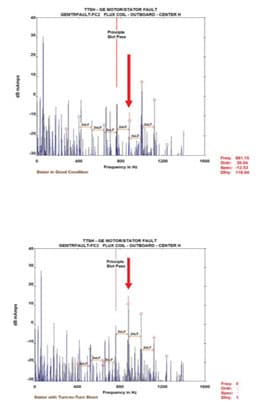
Electric Motor Faults
Industry is reliant on electric motors, whether they be AC, DC, LV, HV, Servos, etc. These items are so critical to the operational and electrical efficiency of any modern production facility. So whether the motor is part of a asset such as a fan, pump, gearbox, compressor, etc, it is imperative that we are able to effectively monitor the motor in question.
Using vibration analysis techniques and equipment, we are able to identify the following fault conditions:-
- Stator eccentricity
- Eccentric rotor
- Rotor problems
- Loose connections
- Power supply and phase problems
At DMS we always recommend that once a potential electrical issue has been detected using VA, that a complimentary electrical motor test is undertaken using our Electrical Signature Analysis equipment.
At DMS we encourage regular surveys at fixed intervals to enable our customers to build up a history of each asset and help to predict when maintenance may be required.